Device Details
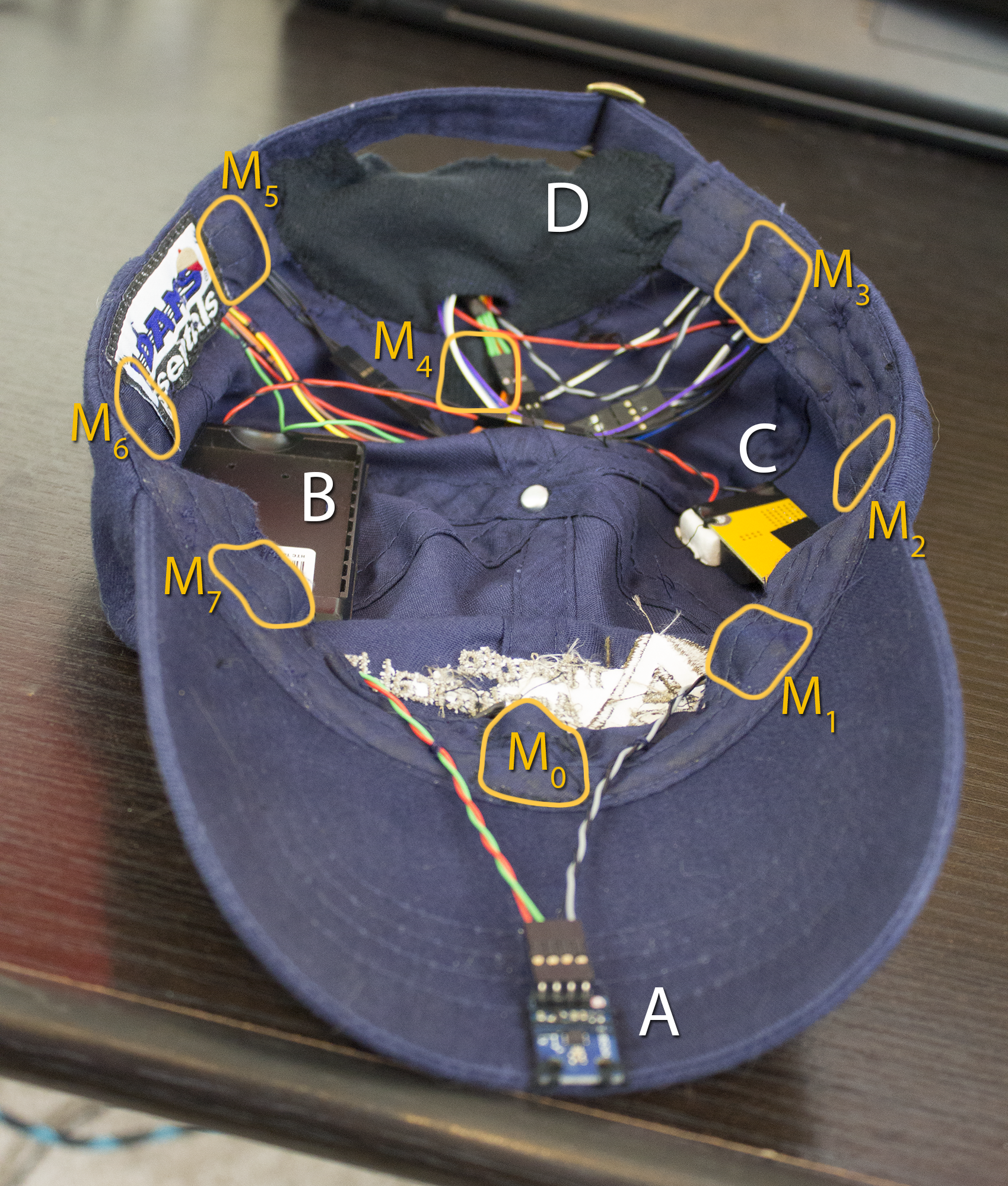 Fig. 1 An annotated view of the inside of the hat containing the
magnetometer (A), battery holder (B), step-up transformer(C), and Arduino (D)
Fig. 1 An annotated view of the inside of the hat containing the
magnetometer (A), battery holder (B), step-up transformer(C), and Arduino (D)
The hat itself contains 8 motors, which are circled and labeled in Fig. 1. I’ve numbered the motors counter-clockwise starting at the motor directly in front of the hat; this numbering relates to how the software selects which motor is running – the pinouts can be assigned arbitrarily in software.
In addition to the motors, there are three basic components: the sensor (an HMC5883L 3-axis digital magnetometer - Fig. 1A), the power source (a cell-phone battery and DC-DC step-up transformer, Fig. 1B & 1C), and the microcontroller (Arduino Nano, Fig 1D). In this page, I’ll go into more details about each of the components and the reasons for the design choices I made.
Hat
I decided to build the device into a hat primarily because hats have points of contact all around the head (not to mention the parts on top of the skull, if you want to indicate a 3-dimensional vector), it’s not unusual to see someone wearing one all the time, and they are large enough to easily conceal batteries and other electronics. Even in the earliest prototype stages, the device still looks like a more or less normal hat. I chose a baseball cap because I thought that the visor would be the best place to mount electronics, but I found that they were less obtrusive when hidden in the crown, so that concern is at least partially alleviated (though it is nice to mount the sensor on a stiff, level surface so that its effectiveness is relatively unaffected by how you are wearing the hat).
I’ve also been considering the use of a knit skull-cap instead — I think this strikes a better balance between extra room for electronics (you could almost certainly fit everything in with minimal unsightly bulging) and not looking out of place in modern society. Obviously a fedora, bowler or top hat gives you a lot of room to place electronics, but these aren’t really practical because they look ridiculous.1 There are two major issues with the use of a skull cap. The first is that they are much warmer than a standard baseball cap - which can cause you to sweat; even if you waterproof all the electronics (which you should probably do anyway in case it rains), I haven’t yet thought of a good way to wash these hats, so you do want to minimize the sweating. The second is that in the summer (or if you live in a warm climate like California or Texas), it will seem very unusual that you are wearing a knit cap all the time, whereas baseball caps are standard attire year round.
Power source
The power in my prototype is supplied by an 1800 mAh battery from a Sprint HTC Evo 4G2, mounted in a wall-charging unit that I disassembled and repurposed. Since Li+ batteries like this one are generally 3.7 V, the voltage is stepped up with a DC-DC step-up transformer, which costs around $5 and generally represents only about 5% power loss.
Vibration Motors
Casing
I bought the motors I’m using some time ago and I don’t remember the exact model number. I would guess that nearly any small DC vibration motors should work, so long as you can supply the appropriate current and voltage. One problem with most bare vibration motors is that the unbalanced weight is exposed, and the rotation can easily be stopped by mild pressure.
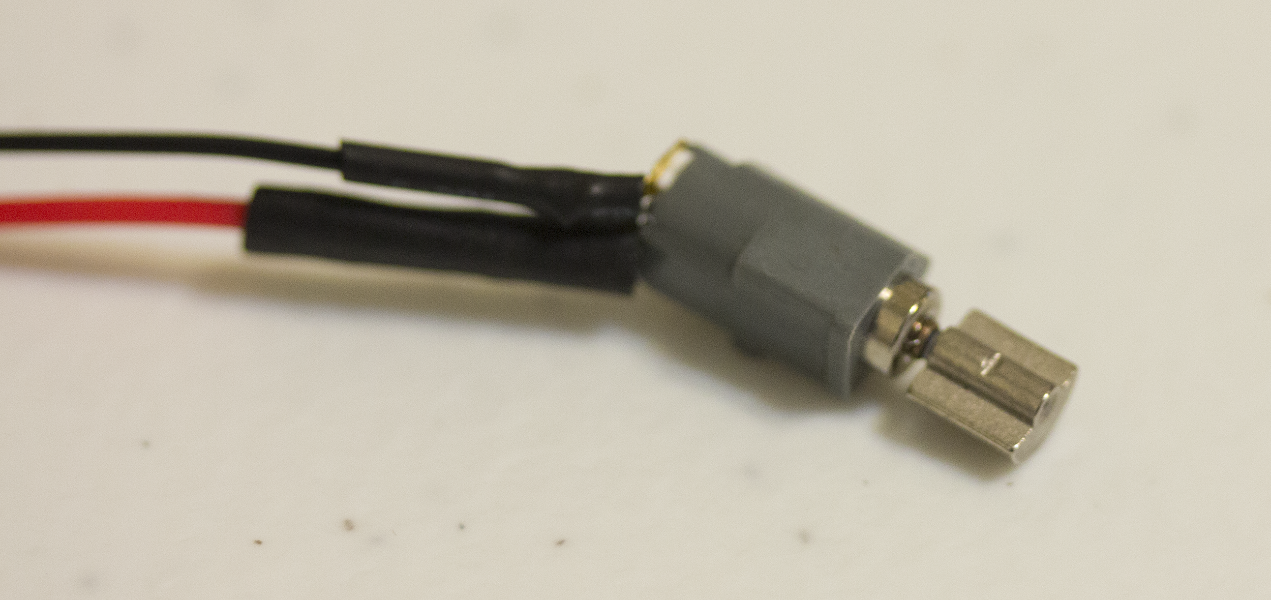
Fig. 2 A bare vibration motor
In order to use it in the HaptiCap, it needs to be in a rigid shell. If you have a 3D printer available, you can make a custom shell, but I’ve found that – at least with the motors I have – the diameter of the motors almost exactly matches the inner diameter of a pencil tube, and so I was able to make 8 shells but cutting up a disused mechanical pencil.3.
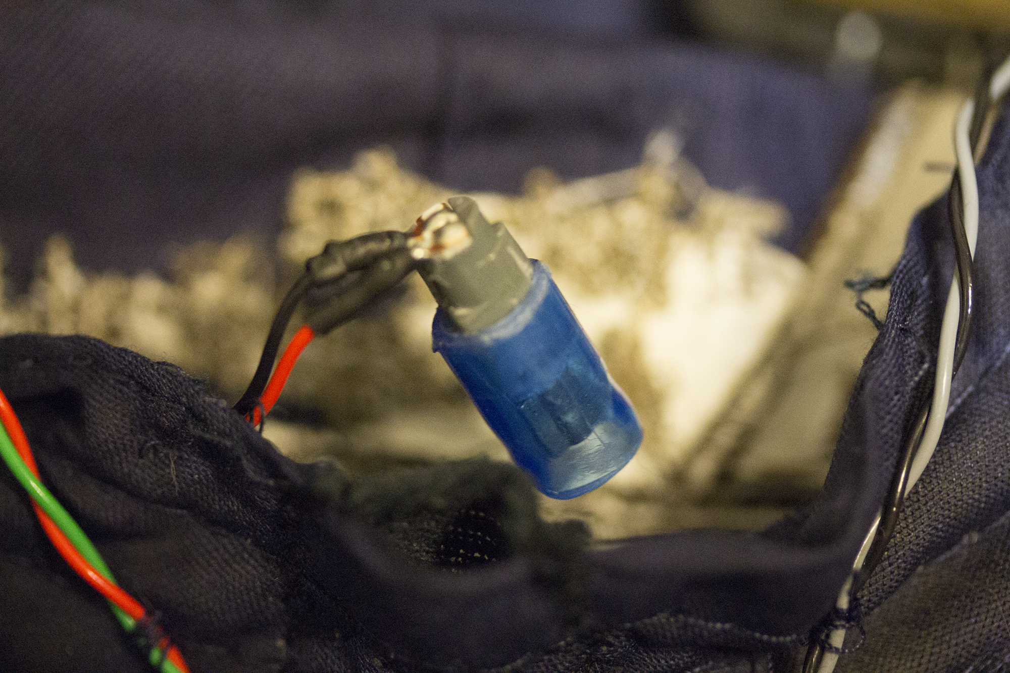
Fig. 3 The vibrator motor in a case.
Another alternative is to use a button type vibration motor, which already has a rigid casing. I have some of these but I have not tested them yet, so I am not sure if the vibration is strong enough to be of use in this application.
Current draw
In the motors I’m using, I’ve measured a resistive load of ~25 Ω, and assuming they are designed to work with 3 V, that’s a constant current draw of 120 mA with a 100% duty cycle. This is considerably more than the 40 mA specified in the Arduino Nano spec, so it may be best to try a design using a multiplexer rather than using the output pins directly4.
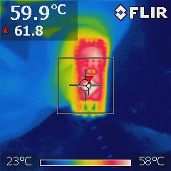
Fig. 4 Thermal image of the Arduino Nano after several hours of continous use.
I’m actually using a SainSmart Nano 3.0 (Arduino clone), and empirically it seems to be capable of providing around 100 mA of current, and in practice I tend to run the motors with close to a 50% duty cycle, so the continuous draw is generally ~50 mA. Using a thermal camera, I noticed that the processor runs a bit hot (~60 °C), but this is not uncomfortable, and doesn’t seem to be causing any damage to the processor itself.
Interestingly, either the microcontroller is extremely inefficient at supplying power to the motors or the motors are not the largest source of current draw in the system (I strongly suspect the former). Even running with a 50% duty cycle (updated every 20 ms), a freshly charged 1800 mAH battery only lasts about 5.5 hours, indicating that the current draw is close to 325 mA, while the motors are only drawing an average of ~ 50 mA. I plan to investigate this with a current probe and some experiments with the algorithms to determine what the main cause of current draw is to try and get the current draw closer to 100 mA.
Footnotes
- ^ I'm aware that there's probably a significant overlap between people who see nothing wrong with wearing a fedora in public and people who would read about a haptic feedback hat, but I'm sorry, if you wear a fedora and you are less than 70 years old, with rare exception you look ridiculous. Getting people to like bigger hats is not a scalable solution.
- ^ Originally I was using the batteries from my old phone, but these were getting a bit long in the tooth and some of them had started to bulge out a bit and fray, so I didn't want to keep using them in such close proximity to my head. I ended up buying 3 more along with a wall charger from eBay for about $15.
- ^ I couldn't find my Dremel and cut-off wheels, so I heated up a box-cutter with a lighter to rapidly cut the plastic.
- ^ This is also useful if you have a microcontroller with fewer outputs than you have motors - the Nano has 8-14 digital outputs (depending on how you want to count). A digital multiplexer can control 8 motors with 3 digital I/O pins, and 16 motors with 4 digital I/O pins.